
Introduction
I have an interest in both model aircraft, and also with the PovRay 3D rendering software. So, as a way of passing the time, and to generate some content for this site, I decided to bring these two together. The idea being that I could document some of the construction details of my glider.
3D Rendering Software
An initial start was made using SolidWorks. Unfortunately, SolidWorks is not available for Linux. Another package that I am familiar with is Pro/ENGINEER. This is available for Linux, but is a little costly.
Blender is an alternative. Blender is a very capable system. Unfortunately, I find it a little too free form. Maybe I just don’t understand it well enough, but compared to an engineering modeller such as those mentioned above, it is designed to be used ‘free hand’.
Povray
Povray is the system I have decided to use. Why? Firstly, it is freely available. It has good documentation. Does a good job of rendering. Finally, I understand it, at least to a limited enough degree to be able to get on with it. It is a bit lacking in the UI department. That can be a strength, once you get past the initial shock. Working in 3D with a text editor is great mental exercise. A bit like doing a 3D puzzle.
Wing Sections
There is a huge array of available sections that can be used to create a wing. I won’t pretend to understand the relative merits of any particular foil shape. For this exercise I browsed the selection at UIUC Airfoil Coordinates Database. Once I found one I liked the look of, the data file was saved to disk. The one selected is described as Selig/Donovan SD7084 low Reynolds number airfoil.
 The data file for this section is a simple text file. Each line gives the x and y co-ordinates of about sixty points on the profile. These points are what I need to generate the required data for povray.
Perl
I must confess that I am not a programmer. I can hack a little, but I generally get lost when what I write is more than a page or two long. That said, I decided that I would use Perl to munge the data file. Before I can really make a start on that, though, I need to work out what I want to achieve in Povray, so that I can munge the data in a suitable manner.
This is not a povray tutorial. Therefore I will cut to the chase, and get to the point. I want to construct my wing object with a mesh object. The code currently looks like this:-
#declare wing = mesh2 {
  vertex_vectors{ #include "vertices.inc"}
  face_indices{ #include "faces.inc"}
}
So I need a perl script that can read the data file of the section, and generate the two include files required by the code above. A little bit of hacking later, and I end up with the code shown here.
Results
The following image is the result of rendering two wing objects that were created using this method.
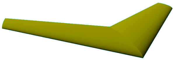
The image is a very simple scene. A close look at the surface reveals some facets. This is cased by using ‘flat’ triangles in the mesh object. A ‘simple’ trick used in rendering to minimise this effect, without having to generate many more triangles, is to adjust the surface normal over the face of the triangle so that the surface normal on the edge of one triangle is parallel with the normal on the edge of neighbouring triangles. Povray can do this, but for that I need to generate a normal vector for each vertex used. Understanding what is required is only part of the solution. Next I need to understand the math to get the normal vectors.
As I don’t expect to fix the surface normal problem any time soon, I will have a go at generating end faces for the wing section. At the moment, I only have a top and bottom surface. If I can generate a closed mesh, it will then be possible to use it CSG operations within povray. This means that it will be easy to make cuts and pockets in the wing model.